Categories
3d printing

Tevo Tornado – updated configuration for Duet firmware v3 series

I’m Jason Firth.

One of the most popular pages of all time on this site is where I connected my Tevo Tornado to a DuetWifi. I’ve been using that 3d printer routinely for years since I put it together, and it’s been rock solid.

That being said, one thing I believe strongly in is running the latest version of software. You never know when you’re going to run into a bug that has been solved years ago, or you’ll need to solve a problem and nobody else can help with your ancient copy of the program.

This year, the duet firmware had a major upgrade from the version 2 series to version 3. The new version has some major changes. Where Version 2 used input and output numbers, version 3 uses specific i/o names. It’s just slightly different.

As a result, you can’t just move to the new version of the firmware and expect it to work, the configuration needs to be modified to deal with the changes to the i/o addressing.

After waiting way too long, I finally got around to making the modifications and testing them. I was able to get the printer back up and running!

When you’re upgrading the firmware from here you will need to do the upgrade in 2 steps: First, you need to install the 3.0 revision to bring your machine to the latest. Next, you need to install the latest 3.x series firmware.

Here is the config.json you can load into the reprapfirmware configurator.I recommend using this with the reprapfirmware configurator to configure anything specific to your unit.

Here’s the final configuration. You’ll probably want to change the wifi parameters before uploading it to your printer if you drop it in directly!

Thanks for reading!

Categories
3d printing

A small practical print I wanted to share

I’m Jason Firth.

3d printing is an amazing tool for a variety of reasons, but one of the big reasons is that you can create something you needed much more quickly than if you couldn’t just 3d print a thing.

I’ve had this YI Home PTZ camera for some time, but the problem is where do you mount it? Every object talking about mounting a YI Home PTZ camera left out a really important piece: the part where you actually mount the camera! They had all these really fancy arms and the like, but that was totally meaningless without the piece to connect to the camera!

A few minutes with a micrometer later, and now I have a nice sturdy mount for the camera. I used a pair of drywall screws to connect it to a surface. Since I wish I was able to find one earlier, I’ve made it available here.

Here’s a link to the STL file

Thanks for reading!

Categories
3d printing

Connecting my new DuetWifi to my new Tevo Tornado

Connecting my new DuetWifi to my new Tevo Tornado including wiring diagram, configuration, mounting plate, and some notes from the conversion

I’m Jason Firth.

 Update: The wiring is the same, but there’s a new version of the firmware that requires a new configuration. I have a new entry with the updated configuration here.

I’ve long believed in Open Source as a concept. I like the idea of a common knowledge we can contribute and help to grow. I can’t contribute a lot nowadays since most of what I work on is proprietary, but occasionally I still get a chance in my off time. I spent a lot of time trying to figure out how to connect my DuetWifi to my new Tevo Tornado. The documentation is straightforward, but there were a few things that caught me off-guard, so I figured I’d share.

Standard disclaimers apply here. Don’t do this. It’ll probably kill your printer. It’ll probably cause your grandfather to come back from the dead and stalk your dreams. This isn’t a product, it’s just a description of what I did, and maybe this might help you if you’re doing what I did. Seriously though, there’s 120vac in this thing. If you don’t know what you’re doing, then you probably shouldn’t be poking around until you read more.

Here’s a nicely printable Wiring Diagram(pdf),Wiring Diagram(dxf)  and the Full configuration files for the Duet’s reprap firmware

Below is a object I designed to bolt into the Tornado’s metal cabinet so you can bolt the duetwifi onto it. Full disclosure, it didn’t print great for me on my delta, it likely needs some tweaking. Thanks to some creative drilling, it worked well enough that I was able to safely secure my board inside the enclosure, but you might want to double check before you start printing it off.

Now, a few things I noticed along the way that are important, and only some of them are included in the drawing for reasons that may become apparent.

First, the wiring I took apart was really bizzare. The case fan was connected to the nozzle heater. The part cooling fan was connected to the e1 heater output. I took all 3 fans and attached them to pin connectors so I could plug them directly onto the board’s fan controller.

I set the part fan as a controllable fan, and the heat sink fan and case fan run thermostatically — if either the nozzle or the bed exceed 50C, then the fans activate at full blast. That seemed the most intuitive to me.

Note that the input for the switches is looking for a 0vdc connection, so while you can (if you don’t mind it looking a bit ugly) use the existing 3-pin connector, you’ll have to move the second wire from the middle pin to the end to connect the input to gnd.

The fans will not work at all until a jumper is placed either from the fan voltage input selector pin to +5VDC or VIN. I show the jumper between the fan voltage selector pin and VIN.

Besides that, once I figured everything out, it was pleasantly simple to troubleshoot the configuration. Because I was doing things this way, I tried to do all the configuration in the reprap configurator utility so anyone else (including myself) can import the included JSON file to make changes using eh same utility. I didn’t do anything manually in the file. I suspect there are further interesting tweaks as you get deeper, but this was entirely meant to be a basic “getting started” info dump.

Thanks for reading!

Categories
3d printing

My new printer, the Tevo Tornado

I’m Jason Firth.

Late last year, I decided it was time to jump into two technologies I really wanted to play with that I’d been putting off for a long time: Virtual Reality, and 3d printing. At the time I selected what appeared to be good choices for both off of Amazon: The Oculus Rift for VR, and the FLSun Delta Kossel for 3d printing.

At the time, I expected virtual reality to be the thing with staying power and for the 3d printer to be a quick toy. What I quickly realized is that Virtual Reality isn’t really for me in a lot of ways — I’ve played many hours, but never really gotten sucked in the way I thought I would. On the other hand, 3d Printing has become a hobby I really enjoy.

The FLSun Delta Kossel was an inexpensive unit. Today you can buy it on Amazon for about $200 CDN. It was really a cheap unit, and I’ve written about my experiences with that unit.

Plutarch wrote of the Ship of Theseus: “The ship wherein Theseus and the youth of Athens returned from Crete had thirty oars, and was preserved by the Athenians down even to the time of Demetrius Phalereus, for they took away the old planks as they decayed, putting in new and stronger timber in their places, insomuch that this ship became a standing example among the philosophers, for the logical question of things that grow; one side holding that the ship remained the same, and the other contending that it was not the same.”

The printer over the course of the year has become like this. I’ve replaced virtually every component, upgraded everything in some way or another. Is it still an FLSun Delta Kossel? That’s difficult to say. What I can say for certain is it’s now a very impressive printer that tends to put out excellent quality prints.

After my year with the printer, I realized how much I’ve enjoyed 3d printing, and I wanted a larger printer that’s a bit more standard so I can start printing larger things and spend a bit less time tinkering with the printer itself.

To that end, I’ve bought a Tevo Tornado. It is a popular model of printer, lots of support out there, and overall I feel it’s going to be a good choice long-term.

My first impression: I’m really impressed with a lot about this printer. The FLSun came in a million pieces and took me a full 2 days to assemble. By contrast, it took me all of 2 minutes to assemble the Tevo Tornado when it arrived. It homed immediately and I found it simple to level the bed, contrasting the Delta’s bed which was always a pain. I’m really happy with the first 15 minutes with the thing.

Before I even get started with this printer, however, I want to replace the main board. It came with an MKS Gen L, identical to the FLSun. There’s no problem with this board for straight 3d printing, but I want a board with a processor instead of a microcontroller, having seen the limitations of the Atmel mega while using my Delta Kossel, and I want a board with built-in Wifi capability. Using Octoprint on my previous printer was a great experience, running around with a memory stick is ridiculous when I can just press one button to start a print. I purchased a DuetWifi clone board. 

I’ll pass on my notes as I work with this new printer.

Thanks for reading!

Categories
3d printing

You can’t take the tradesman out of the…

I’m Jason Firth.

Another quick post to share my latest improvement for my 3d printer (again). I wasn’t very happy with how the cables hanging. In cabinets we often use sticky backs or slotted rail to clean up cables, I decided to use a similar approach on the printer. Here’s the design you can use on tinkercad:

Categories
3d printing

Updated spool holder

I’m Jason Firth.

Here’s an updated spool holder. I took some ideas from Geoff King who printed up a modified version that fit with more spools. It bolts directly onto the screw holes for the original holder.

Categories
3d printing

Next step

I’m Jason Firth.

I printed off a set of braces for the towers of my Delta printer, and after installing them, found that the printer was all of a sudden failing prints. The kapton tape on my bed was utterly destroyed twice in a row, and the print I was trying to do just didn’t work.

My first instinct was to take a look at the home switches. They were wobbling around, so I figured part of the problem could be that my homes weren’t consistent.

I swapped the square bolts that come with the FLSun printer with actual T-Bolts. I immediately realized there was a problem: The bolts were not holding the part in!

I discovered that the back of the switch had these ridges meant to hold them into the 2020 strut.

![undefined](img20180128162318_2_o.jpg)

I realized the easy way to fix it was to cut away part of the ridge. I used a simple razor blade from Home depot:

![undefined](img20180128162528_0_o.jpg)

Afterwards, the t-bolts I purchased fit properly:

![undefined](img20180128162602_0_o.jpg)

The switches locked in solid after this.

problem: My prints were still failing!

So I looked further. Next up I realized a basic maintenance problem: My belts were very loose. It worked much better after that, didn’t slam into the bed.

However, the print still failed, even though all these maintenance items were improved.

The final solution was to increase the layer height of my prints. I had it set to .06mm, but it appears that once I started tightening up everything, the printer simply isn’t capable of printing such thin layers. Perhaps in its sloppiness it was just barely slopping its way into each of the next layers.

Categories
3d printing

3d printers again…

I’m Jason Firth.

Yesterday, I had a revelation about my new printer. I was pretty happy with the prints I was getting (happy to be getting any prints at all, in fact) but the quality wasn’t quite where I wanted it.

I ran a check of the extruder calibration and found it substantially out. I asked for 100mm, but got 57mm instead.

I was already looking at calibrating the extruder, so I switched to the Marlin AC branch. That branch contains the latest developer patches.

Along the way, I had to move my config changes to the new firmware, so I had a deeper look. One change I made is to reduce the “slow” speed while calibrating. The stock settings shook the whole thing. I also increased the number of calibration points and changed the calibration routine to take each measurement 3 times.

One of the additions to the marlin-ac was automatic bed levelling. I assumed the auto calibration took care of levelling, but it seems that’s a different feature.

Someone in the flsun Facebook page suggested that my “delta kossel” and the “mini kossel” I keep reading about might be the same printer. It does seem plausible on second thought. However, it means that the example config is just completely wrong.

The other thing is that the flsun YouTube page appears to call the delta kossel and mini kossel different things. It’s difficult to figure out whether the two are the same or not.

This speaks to a fundamental of maintenance: defining your equipment. Giving it consistent naming, giving it a unique identifying number that functions within a system. For a company with perhaps 9 different products, this ought to be trivial. Perhaps a digit for product category (3d printers), one for product type (delta kossel), one for the subcategory (mini/standard/jumbo), a digit for model number, and a digit for revision number. “3ks1a” – easy. Then everyone can search for “3ks1a” and find Information directly relating to that printer.

In industrial automation, the ISA 5.1 standard defines similar naming. In industries around the world, this convention is used to name instruments in an immediately identifiable fashion.

Let’s look at a typical designation:

66-FIT-123

The 66 part of the above is area number. Very few plants are monolithic. Most consist of a certain number of defined areas with defined functions. These areas often have a single number associated with them. If 66 were for a certain power boiler, for example, anyone in that plant would immediately recognise that the instrument existed in that power boiler.

The second part, “FIT” above, is a standardized designation based on the ISA 5.1 standard. In this case, the first letter tells us the process variable. In this case, “Flow”. Other common process variables are Temperature, Pressure, Analytical, or Density. Each represented by the first letter of the word. The second letter above is “Indicating”. It is a modifier telling us that the instrument has a display. Finally, the last letter is “Transmitter”. This speaks to the function of the device. Often you’ll see Switches, Valves, or Elements. Sometimes you’ll see a Y, which indicates “special function relay”

Finally, the number “123” above represents the unique loop number. Every loop in the area will have a unique number, making it trivial to look for loop sheets, wires in a junction box, or PLC code.

In terms of the name you’d give it, I prefer following a few general rules.

1. Name for humans. This means naming things using natural language, and in a way that people can read. I’ve seen colons, dashes, And underscores in names. There’s no need for that. I’ve also seen things named something nobody calls something. Either correct your name, or change what people call the thing.

2. Name precisely. Calling stuff pump #1 is tempting, but makes things too difficult when trying to refer to something. “Boiler #10 feed water pump #2” tells someone everything they need to know about that device. Calling the printer the “Delta Kossel” is too broad. Every printer of this type is a “Delta Kossel”, and it appears the company has multiple kossel style printers.

3. Name consistently. Create a nomenclature or taxonomy and follow it. Don’t refer to the same device with six different names. In this case, the “Delta Kossel” and “Mini Kossel” might be different things. If they are, that’s fine. If they’re not, that’s a major failure of naming.

Anyway, I’m done playing with the printer until next weekend. Looking forward to the next steps. I’ll keep everyone updated.

Thanks for reading!

Categories
3d printing

3d printer, day 2

I’m Jason Firth.

I apologize in advance for the photos. No idea why they came out so bad.

Last time, I talked a bit about setting up my new 3d printer, an FLSUN Delta Kossel. The first day consisted of fighting with the firmware that was set up without any limits, and with some seriously wonky default settings.

I was able to complete my first 3d print, a ring from thingiverse, and then moved onto my second 3d print, a ball valve I designed:

![undefined](494367944833638131_0_o.jpg)

Unfortunately, it didn’t print very well, and after printing successfully once, I wasn’t able to get it to print at all again.

I still had a few problems. The head wanted to dig into the bed. I tried to tape some magazine stock to the bed to protect the head and I tried to calibrate the bed that way, but that was a pretty poor solution. What I discovered is that there were a few problems with what I was trying.

The unit came with leveling springs, and the instructions on YouTube suggested I install them. This turned out to be a bad idea, because the nozzle contains a spring as well,and the two were fighting each other. I took out the spring, and because I’m concerned about the heated bed touching a bunch of plastic, I took one of the spare square bolts and used it as a spacer:

![undefined](removesprings_0_o.jpg)

Next, I wasn’t happy with the auto calibration. The entire unit shook dramatically as it auto calibrated because of the huge amount of force needed to overcome the spring. I looked at the head and realized I didn’t have *one* adjustment, I had *two*. The silver set screw that set where the button releases, and the black set screw that set the spring tension:

![undefined](setscrews_0_o.jpg)

I realized I’d have to calibrate the nozzle before I could run a printer calibration.

First, I loosened the silver screw until I heard the switch click, then I tightened it slowly until I heard it click again. I pressed the nozzle to prove the switch was actuating properly, because a couple times I just tightened it until I heard it click again but it didn’t reset with nozzle movement.

Second, I loosened the black set screw until the switch opened, then tightened it back up until I heard the switch close again.

After calibrating the print head, I was getting much better calibrations that didn’t shake the unit so badly.

Finally, to deal with the print head jamming itself into the print bed, I discovered a setting called Z-offset. I was able to change the z-offset from the unit faceplate.

First I went to the control menu:

 ![undefined](controlmenu_0_o.jpg)

Then the motion menu:

 ![undefined](motionmenu_0_o.jpg)

and Finally set the Z-offset:

![undefined](zoffsetmenu_0_o.jpg)

I figured out the z-offset by setting my height (I used the faceplate in the prepare menu, but you could easily use Repetier to do it from your computer) lower and lower, until I couldn’t slide a piece of paper under the nozzle anymore. I set the Z-offset to the number of mm.

The final improvement I made was to place a fan near the bed. The unit has a fan built onto the nozzle, but this didn’t seem like a bad idea.

I was finally able to consistently make successful prints. Early on, I designed and built these clips so we can screw our undercabinet lighting to the cabinets:

![undefined](lightclip_0_o.jpg)

And by the end of the day I had printed a spool holder I designed:

![undefined](latestprint_0_o.jpg)

I was really happy how this one turned out. Not so happy about how the picture turned out, mind you. No promises how it will hold up once I place a 1kg spool on it instead of the smaller provided spool.

A few things I’ve discovered in a day of printing:

Don’t waste time trying to save material. A 1kg spool of filament has about 330m of filament. All the designs I’ve been printing use less than 10m of filament.

You see a lot of prints that look like they’re really substantial, but they might not be. The prints might be completely hollow inside. The above print has a 5% infill, so very little inside.

Shell thickness is your friend. I printed a tube with a 0.5mm shell thickness, and it was a great demo, but very quickly broke. I printed with 1mm shell thickness, and everything was much more substantial and is holding up much better. Given the choice between infill and shell thickness, I’ll choose shell thickness every time.

I didn’t need a raft or anything once I had the printer well calibrated. Suddenly the bottoms of my print were good by themselves.

Even though professional designers using molded plastic might use voids to conserve material, that seems to be a really bad idea here. I created an earlier spool holder that used a thick column with voids, and it was a really complicated print — it was constantly retracting and spooling out and ended up being really messy.

Today’s prints pushed the limits of a 40mm radius print bed, so I spent some time doing some tests. I figure I can safely print to 70mm without the print head or arms contacting anything, so I increased the print radius to 70mm in the marlin source code and re-uploaded.

I had a calibration error I couldn’t figure out — my Y axis was off, but only my Y axis. A post on the marlin forums suggested moving to the latest, so I moved to the nightly and re-uploaded. That worked perfectly. After upgrading, the printer calibrated happily and I’m ready for more printing tomorrow.

Because I don’t want someone like me to have to deal with the annoyance that was my first day, I took the configuration headers and submitted them to the marlin project for entry into the examples file.

Categories
3d printing

3d printing

My FLSUN kossel 3d printer first impression

I’m Jason Firth.

This year I wanted to go on a bit of an adventure, so I got a couple of toys. One is the Oculus Rift VR system, the other is the FLSUN delta kossel 3d printer with a heated bed. I purchased both from Amazon Canada with Prime shipping.

The Oculus is more a consumer entertainment device, so let’s talk about the 3d printer. It’s a consumer device, but it’s interesting enough on it’s own.

I had never done anything with 3d printing before this weekend. It’s been on my wish list for years, but I didn’t feel I was quite ready until recently. This journey is still therefore fresh, I am not coming into this after I’ve learned everything there is to learn.

On Friday night, I got off the plane from work and found the printer box waiting for me. I couldn’t wait, I immediately ripped it open and started reviewing the contents. The printer arrives completely disassembled.

Being a proud tradesman, I decided early on that I wanted the wiring to be built and wired in a neat and workmanlike manner as much as is physically possible. This turned out to be more difficult than I’d hoped later — most of the wires attached are far too long, and a couple were just a little too short for a good install. In retrospect, I likely would have built it differently knowing what I know now. In particular, I would have planned from the beginning to have an electrical box on the side and run the extruder wires directly through it. But I’m getting ahead of myself.

The box allegedly came with instructions, but I found the written directions disjointed and incomplete. The best bet was following the videos on YouTube. The video was essential to putting the printer together, but as time went in the level of detail started to slip. Eventually they stopped telling us which screw sizes to use and when it came time to wire the board it just said to look at the wiring diagram.

If you follow their directions perfectly, you’ll end up with a rats nest of wires. There’s very little mention of routing the wires except for the end stop switches, and the instructions assume you’ll jam the box on the table under the heated floor. I ended up pulling apart some of the printer after assembling to route the cables in the aluminium rails.

The kit comes with virtually everything you’ll need to build the printer. The bolts are all metric and I didn’t realize they’d done that until I’d made it part way through. It was a pleasant surprise.

I purchased a 6x6x6 electrical box from home Depot and 2 strain relief connectors. In retrospect. I needed 4 strain relief connectors: 1 for the wires from under the heated bed, one for the wires from the extruder and the 12vdc power, one for the USB cable, and one for the pair of ribbon cables going to the display. I’m reasonably happy with the result on the outside, but inside the box is a rats nest of wires because some of the wires are too short.

I had a premonition once the wires were connected and plugged the 12v power supply into the wall for a smoke test. Blue Sparks immediately started sizzling and flashing from the power supply! I quickly unplugged the supplyand discovered that the screw terminals on the supply had not been soldered down. Gives me reason to question that QA sticker. Sort of a big detail to miss. I soldered the screw terminals in and after that was getting 12.00vdc on my meter. Good enough!

There are numerous extra parts not shown in the video. Fans, heat sinks, and much more. I’m happy to have parts, but I’m concerned that I’m hurting something by not installing these parts. Before I do major printing, I intend to install at least the heat sinks.

Before I got the printer, I started reading and chose tinkercad as my first 3d modelling program. It’s very simple, which I feel I need at this point. I designed a simple ball valve as my first print. I’m hoping to eventually 3d print stuff like this. Tinkercad is easy to use, web based software from Autodesk. Once you’re happy with your object, you can Immediately export it as a file the 3d printer software stack can understand.

The board contains an atmel microcontroller, and is programmed using the Arduino software. The firmware it comes with is called “Marlin”, and 99% of the work is already done. That last 1% is a doozie.

There is a buzzer, a knob, and a button on the front panel. The buzzer does what you’d expect, the knob is used to control the units interface (spin it left and right and press to select), and the third button immediately resets everything. I treated that third button like an emergency stop, and I needed it a lot at first.

I downloaded the latest Marlin source code and used the example configuration for the flsun 3d kossel mini. All the configuration is in 2 files, a configuration header and an advanced configuration header. You’ve got to tweak them in the Arduino software before you start.

There’s a that allows you to access the calibration menu from the faceplate. I uncommented that early because it made it easier doing all the cal tests that I ended up doing.

The example configuration for the kossel mini in Marlin 1.1.18 was dangerously wrong for my printer. The more immediate problem is that the delta radius was substantially off. This meant that the print surface was extremely convex. In the middle of the print surface, I would be touching the print surface with the print head, but at +50 or -50 on the x or y plane I could fit my finger beneath the print head. I measured the radius from the print head to the pivot point on the side rail of one of the arms, and I think I found a number somewhat like 135mm. The number was very different from what the config had by default. With this massive error, the printer could not auto calibrate. The second problem was the delta height was too low. It was set for 250 or so. This caused it to try to find the bed level in the middle of the air. I set it to 318 and the height calibration worked, somewhat. More on the height later. Finally, the printable radius was set to 110. This is the dangerous part. The printer simply cannot move like that. Ultimately, I might be able to set this to 50-55, but after getting burned a couple times jamming my print head outside the print area and jamming the e-stop, I set it to 40 for now. The second number that was causing the calibration to catastrophically fail is the cal radius. It was set to something like 90, Which is simply outside the range of this printer. I set it to 36.

All this took time to figure out — about a day, After setting these values and uploading the resulting firmware, I was finally able to get the machine to complete an auto calibration cycle.

There’s still one problem: the bed height is coming up too low. My reading suggests that the problem is the spring dampeners on the bed. The nozzle has a spring and a limit switch, so when the nozzle touches the bed it is supposed to push the nozzle up and actuate the switch while calibrating. With springs on the bed, the bed bounces back as well, causing inaccuracy on the calibration because the bed moves down. I’ve been able to print by manually decreasing the bed height, but the inaccurate calibration has also caused inaccurate measurements on the bed level. As a result, the nozzle digs in on one side and floats on the other. I used thick magazine paper as my bed material to reduce damage to the head if it does dig in for my first 2 prints. When I get home I’m going to mount the bed solidly to the frame to eliminate the vibration error. Seeing what masking tape does on a heated bed, I purchased some kaptan tape for future prints.

Out of the box, there’s nothing to hold the reel of filament. Once I have the printer working reliably, one of the first things I want to print is a reel holder. In the meantime, I noticed that the rails are wide enough to hold a jeweler’s screwdriver, so I am hanging the reel off a jeweler’s screwdriver for now.

The software stack the printer uses on windows is called Repetier-host. You can download .STL files from thingiverse and directly open it in Repetier. From there you choose print location and size, then send the print to software called a “slicer” which turns the 3d model into instructions the printer can print, called g-code. From there, the slicer can directly give the instructions to the printer over USB, or it can save the g-code file to an SD card. You can then directly place the SD card into the printer and print using the front panel.

I had to fiddle with a couple settings. First, I had to set the printer surface to be circular, and I had to fiddle with the slicer, telling it my filament size, extruder size (.3 it seems), and a couple other options.

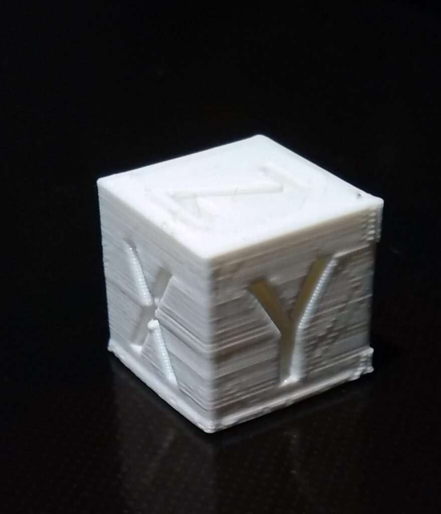
Having done all this, I finally successfully printed something!

That said, it was more dumb luck than anything. I successfully printed a little ring for my wife, then I printed the valve I designed, but after that I was having issues getting the bed to stay down.

I discovered 3 things: first, the aforementioned bed springs being a problem. Second, the extruder temperature was too low causing the bed to have problems adhering. Third (paradoxically), once the filament left the extruder, it stayed too hot for to long, so the prints melted into a mess that looked like a wax sculpture of what I wanted melting in a hot car in the sun.

For a first attempt, I’m pretty happy. If it was easy, it wouldn’t be nearly as fun.

I’ll keep you posted. Thanks for reading!