Connecting my new DuetWifi to my new Tevo Tornado including wiring diagram, configuration, mounting plate, and some notes from the conversion
I’m Jason Firth.
Update: The wiring is the same, but there’s a new version of the firmware that requires a new configuration. I have a new entry with the updated configuration here.
I’ve long believed in Open Source as a concept. I like the idea of a common knowledge we can contribute and help to grow. I can’t contribute a lot nowadays since most of what I work on is proprietary, but occasionally I still get a chance in my off time. I spent a lot of time trying to figure out how to connect my DuetWifi to my new Tevo Tornado. The documentation is straightforward, but there were a few things that caught me off-guard, so I figured I’d share.

Standard disclaimers apply here. Don’t do this. It’ll probably kill your printer. It’ll probably cause your grandfather to come back from the dead and stalk your dreams. This isn’t a product, it’s just a description of what I did, and maybe this might help you if you’re doing what I did. Seriously though, there’s 120vac in this thing. If you don’t know what you’re doing, then you probably shouldn’t be poking around until you read more.
Here’s a nicely printable Wiring Diagram(pdf),Wiring Diagram(dxf) and the Full configuration files for the Duet’s reprap firmware
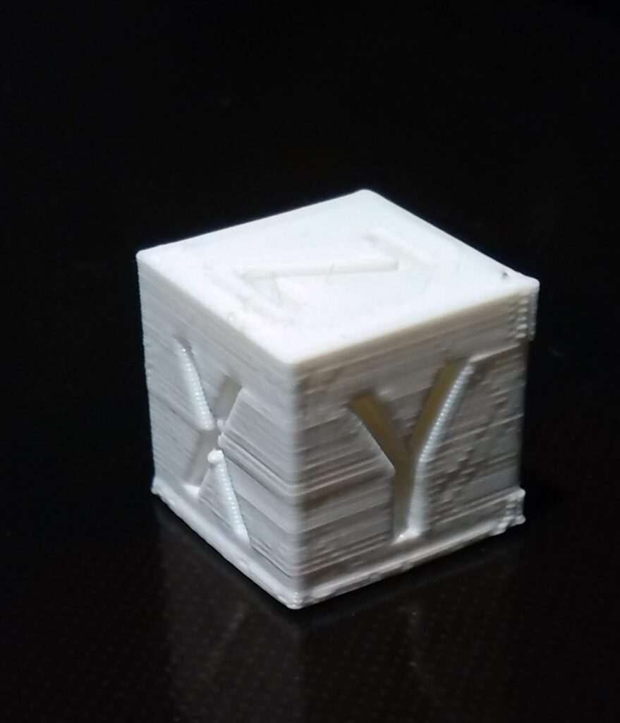
Below is a object I designed to bolt into the Tornado’s metal cabinet so you can bolt the duetwifi onto it. Full disclosure, it didn’t print great for me on my delta, it likely needs some tweaking. Thanks to some creative drilling, it worked well enough that I was able to safely secure my board inside the enclosure, but you might want to double check before you start printing it off.
Now, a few things I noticed along the way that are important, and only some of them are included in the drawing for reasons that may become apparent.
First, the wiring I took apart was really bizzare. The case fan was connected to the nozzle heater. The part cooling fan was connected to the e1 heater output. I took all 3 fans and attached them to pin connectors so I could plug them directly onto the board’s fan controller.
I set the part fan as a controllable fan, and the heat sink fan and case fan run thermostatically — if either the nozzle or the bed exceed 50C, then the fans activate at full blast. That seemed the most intuitive to me.
Note that the input for the switches is looking for a 0vdc connection, so while you can (if you don’t mind it looking a bit ugly) use the existing 3-pin connector, you’ll have to move the second wire from the middle pin to the end to connect the input to gnd.
The fans will not work at all until a jumper is placed either from the fan voltage input selector pin to +5VDC or VIN. I show the jumper between the fan voltage selector pin and VIN.
Besides that, once I figured everything out, it was pleasantly simple to troubleshoot the configuration. Because I was doing things this way, I tried to do all the configuration in the reprap configurator utility so anyone else (including myself) can import the included JSON file to make changes using eh same utility. I didn’t do anything manually in the file. I suspect there are further interesting tweaks as you get deeper, but this was entirely meant to be a basic “getting started” info dump.
Thanks for reading!