
Siemens WS300 teardown
I’m Jason Firth.
I had an opportunity recently to tear apart a Siemens WS300.

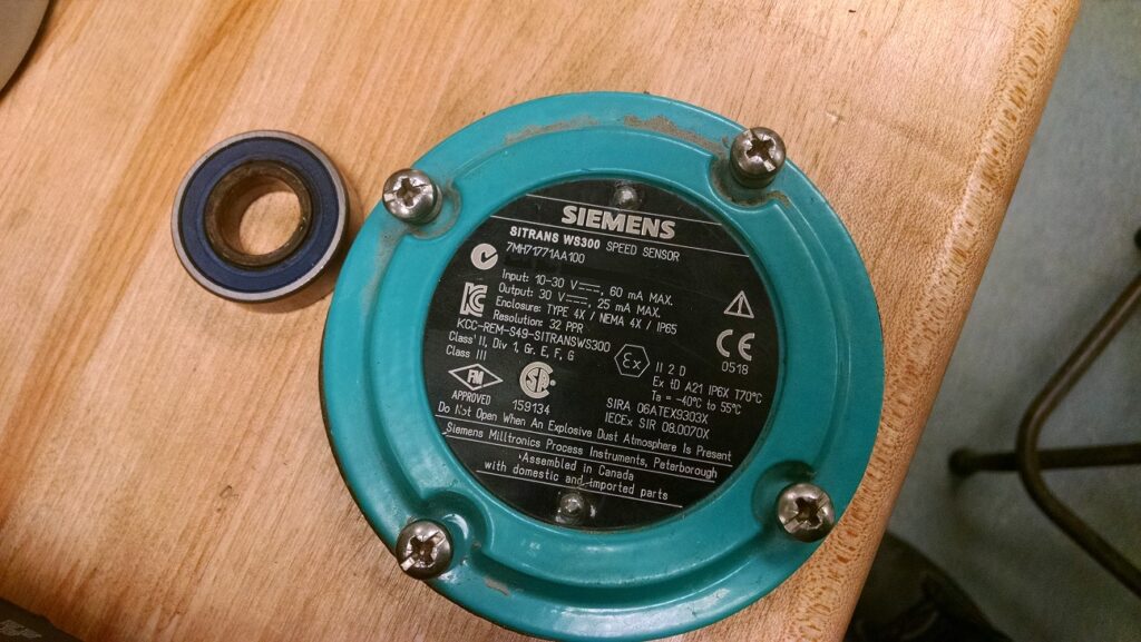
I was hoping to troubleshoot a problem with it, and in the process I learned a bit about how they were put together.
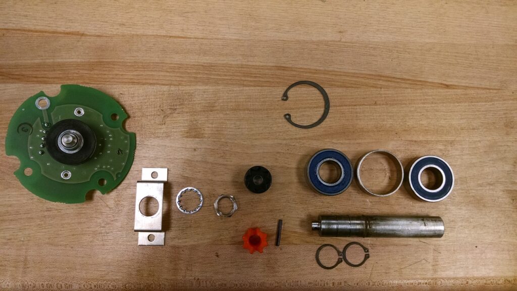
Here you can see the mechanical components. The thick metal shaft is the part that sticks out of the sensor. It has a single bearing (the big round circular thing with the blue plastic) held in place by a retaining clip. Next, there was the circular piece of metal, and another bearing, which is then held in place with another retaining clip. The shaft with the bearings slides into the housing, and is held in place by the large retaining clip. The very end, where the shaft becomes small, has a little metal pin in it, which acts like a handle.
The orange part of the coupling has a slot cut in it, which slides over the shaft, holding onto it. Then, the orange part connects to the black coupling, which is held onto the binary encoder. The encoder is held to the circuit board with the metal clip, which screws onto the board, and holds the encoder with the large nut and locking washer.
The rotary encoder might look like a resistive potentiometer, but it is something a bit more complicated. Instead of changing from 0 to 100% resistance over the course of its range, it consists of a pair of lines which change differently in response to rotating in different directions.

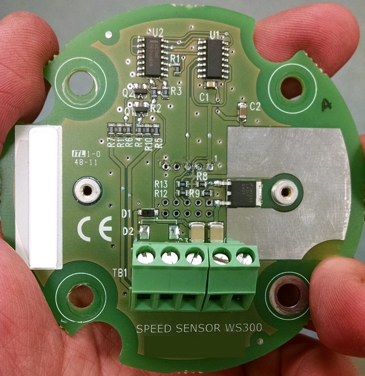
Here’s the circuit board. Let’s look at some of the components:
There’s a LM317. This is an adjustable voltage regulator.
The AC74 looks like a dual flip flop chip (the model number isn’t exactly the same, so it’s possible it isn’t the right chip). This makes sense, because the output of this transmitter is a pair of signals: one changes when you turn the sensor in one direction, the other changes when you turn the sensor in the other direction. This chip is probably where our final logic comes from.
There are two transistors, Q1 and Q2. These probably take the logic signals from the AC74 and convert it into a full voltage signal.
The HC132A chip seems to be a quad NAND gate. You can create a lot of different logic using a few NAND chips, so this makes sense.
Knowing what these parts are, we now have a general idea how this works: The input voltage is regulated down, then some NAND gates and flip flops are combined to provide a pair of pulse outputs.
We determined that the rotary encoder was destroyed, since we now understood how to feed +5v signals to force the board to operate we were able to confirm that the electronics functioned and the sensor did not.
I hope you found this look at a common instrument as interesting as I did.
Thanks for reading!