Category: Process Control

  • Modbus Plus communication to your PC without a $2000 USB Dongle

    I’m Jason Firth.

    A few months back, I had a discussion with someone about how to communicate with a PC over Modbus Plus without breaking the bank. I decided to take the highlights of that conversation and bring them together in a blog post so others might be able to use the information.

    Modbus Plus is still a widely used protocol in industry where Schneider Modicon PLCs are in use. However; it’s not a cheap protocol to work with. A USB Modbus Plus dongle for your PC will run you over $2000!

    That’s a lot of money if you just want to look at some bits in the PLC. Today, I want to look at some other options.

    Modbus Plus is a completely different protocol than Modbus.

    Modbus Plus uses a proprietary signalling standard, where Modbus generally uses RS-232 or RS-485. Modbus Plus supports routing, where Modbus has no networking features. Modbus Plus requires a DSP to handle the communications, where Modbus can use a standard UART. Modbus Plus is peer-to-peer, where Modbus is master/slave. Modbus Plus uses a token passing system to ensure everyone gets a turn on the line, where Modbus doesn’t have any mechanisms (hence requiring the master/slave architecture where the master dictates who will speak). You just set your addresses, and all the devices will start talking. The Bridge Multiplexer acts as a gateway between the two protocols.

    Modbus Plus allows for routing between devices called Bridge Pluses. The way you do this is by defining the modbus plus address of each bridge plus you pass through. For example, if you have node 1 on a modbus plus network with a bridge plus node 64, and there’s a node 32 on the other side you want to communicate with, you’d be communicating with 64.32.0.0.0

    So to make sure your modbus devices can talk over a modbus plus network, you need to map the single values to modbus plus addresses.

    Modbus plus requires a DSP. This means that no matter what, you’re going to need a dedicated piece of hardware to communicate on the network. You can’t just slap an RS-232 pigtail together and hope it will work.

    Here are two potential options: first, if you get a PC with an ISA slot, the cards are quite inexpensive. I found some on eBay for 100-200 USD. A PICMG backplane can use an ISA slot, and there are industrial main boards still available. The downside to this is that you may be stuck using a very slow PC just to communicate with your one PLC.

    Another option is a bridge multiplexer, which converts modbus plus to modbus. It takes a bit to put together, but it should work. I found a bridge MUX on eBay for 100usd when I first investigated this option. Today, I’ve found them for under $250 on eBay.

    The manual really overcomplicates things.

    There are models on page 10 of the manual — nw-bm85-000; NW-bm85C000; and NW-BM85D008 which don’t need a special progran. You don’t need to make a C++ program. You connect to one of the serial ports (I think the second one) and put the bridge into programming mode by flipping a DIP switch on the back, then it gives you a fairly nice and easy menu based interface to configure what it does.

    You’ll need to figure out master/slave stuff, because modbus is client/host but modbus plus is peer to peer, but it should be very doable.

    The master in a modbus interaction is the device that actually sends the commands. For example, I programmed a modbus TCP library, and in that case, the device that initiates the connection is the master: you connect, then either tell the device you want to read or write a coil or register, then the slave device that you connected to will respond with either a success/fail message for a write, or the data you wanted or an error message.

    The Peer-to-peer feature is relevant because it means nothing on the Modbus Plus network is a master or a slave. They’ll just take care of communications on their own. In my tests, the only problem I could cause to the modbus plus network is if you set your bridge mux to the same address modbus plus address as something else on the modbus plus network. If you set a wrong modbus setting in the text interface, all you’re going to do is not communicate with the Modbus Plus network over the Modbus port.

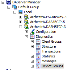
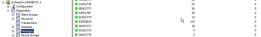
    Here’s how I managed to talk to a PLC using my PLC software and a BM85 connected to my serial port.

    I set my modbus plus address of the BM85 to 2 by turning the first switch on and the rest off.

    I entered config mode using the dip switch on the back

    Once the screen loaded, I entered the following commands:

    V1

    P1

    Tm

    B9600

    S1

    Re

    Mr

    Y1

    V2

    E1 01 20 00 00 00 00

    V4

    W

    Press y to confirm

    Turn off bm85 and return config mode to run mode.

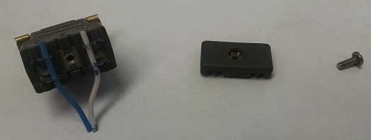
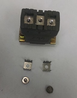
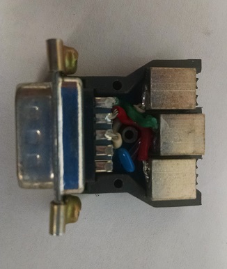
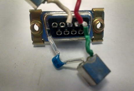
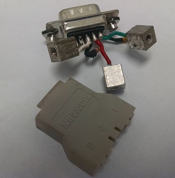
    One key thing seems to be the rs-232 cable from the PC to the BM85. I used a 990NAA26320 but the wiring diagram should work ok to make a cable similar.

    So what you’ll have is:

    Your PLC, and bm85 daisy chained together on the modbus plus network.

    Your PC plugged into the BM85 on modbus port 1.

    Your BM85 set to a free Modbus Plus port

    Your PLC set to whatever it is (no change)

    Your bm85 configured using the keystrokes above, in run mode.

    I use Fasttrak softworks, so I open it up and set it up to look at the COM port. Next, I did a PLC connect and did a port scan. I saw the BM85 and the PLC. Next, I chose the PLC from the list and hit connect. I was talking to the PLC!

    So what’s going on: In this situation, you have two types of communication going on: The Modbus Plus communication, and the Modbus communication. So the PC acts as the master in a modbus communication. It sends commands to the bridge mux. The bridge mux, while configured with the master option, is actually acting as a slave on the modbus port: It is only responding to commands the PC master provides. The BM85 receives the message, and saves it so it can send a corresponding message on the modbus plus network to the PLC.

    Now, you have another network, the Modbus Plus network. What’s going on there is, each device gets a token which is its turn to speak, and it says what it has to say on the modbus plus network and passes the token to the next device.

    If the PLC and the BM85 are all configured, all this is transparent behind the scenes.

    So let’s talk troubleshooting.

    If you seem to have all the right pieces connected in the right way, I’d start from the outside and work my way in.

    Can you connect to a PLC using your directly using the serial cable? If so, then you’ve proven the converter and the cable. I know that those serial converters can be flaky — If you plug them into different USB ports, they’ll use different COM addresses. You can check device manager to make sure you’re configured for the COM port you think you’re using.

    What is your BM85 Modbus Plus LED doing? The following are the flash codes for Modbus Plus:

    Six flashes/second Normal operating state. All nodes on a healthy network flash this pattern.

    One flash/second The node is off-line. After being in this state for 5 seconds, the node attempts to go to its normal operating state.

    Two flashes, then OFF for 2 seconds The node detects the network token being passed among other nodes, but it never receives the token.

    Three flashes, then OFF for 1.7 seconds The node does not detect any token passing on the network.

    Four flashes, then OFF for 1.4 seconds The node has detected another node using the same address.

    If the light is flashing 6 flashes per second, then it suggests that your Modbus Plus network is working correctly.

    Thanks for reading!

  • What’s inside a Modbus Plus connector?

    I’m Jason Firth.

    Eventually, I knew I would be writing at length about Modbus Plus.

    Modbus Plus is the protocol that Modicon created to supersede the Modbus protocol. It has some superficial similarities, but it quite different under the hood.

    Modbus is a Master/Slave protocol. One device is the master, and tells which Modbus slave to talk. By contrast, Modbus Plus is a peer-to-peer protocol. Each Modbus Plus device can request data from any other device.

    Modbus doesn’t have any real way to manage congestion, because there should never be congestion. The master requests data, and will not request more data until the first is sent. By contrast, Modbus Plus uses a token passing mechanism, where each node in the network gets a chance to talk, then once it has finished talking it will pass the token to the next node.

    Modbus generally relies on RS-232, RS-422, or RS-485 signalling to communicate. By contrast, Modbus Plus uses a proprietary signalling protocol over a single twisted pair of wires. Modbus can be implemented using a standard UART, where Modbus Plus requires a special DSP.

    Physically, Modbus Plus is a bus protocol. All devices are electrically connected to every other device on the Modbus Plus network through an electrically continuous shielded twisted pair cable.

    Modbus basically doesn’t have network capability by itself. However, Modbus Plus has basic networking capability. Using a device called a “Bridge Plus”, you can connect different Modbus Plus networks together. The address you use to connect to a device is actually the path of devices you follow to get to the other device. If you were connecting to device 1 on the local Modbus Plus network, then you’d connect to 1.0.0.0.0. If you were connecting through a bridge multiplexer at address 2, then you’d connect to 2.1.0.0.0. If you went a step further and connected to 1 through yet another bridge multiplexer across the network at address 3, then you’d use address 2.3.1.0.0.

    The data transferred using Modbus and Modbus Plus is roughly equivalent. You can send and receive inputs and coils, inputs and registers. There are also other operation codes in the protocol for diagnostics, or programming PLCs, or a number of other functions.

    There are 3 types of connector routinely used for Modbus Plus. The AS-MBKT-085 inline connector takes a Modbus Plus cable and stabs the wires, to establish continuity. The 990NAD23000 Tap takes that cable and stabs the wire into a “tap”, which connects to a moulded cable which connects to the device. The 990NAD23020 or 990NAD23021 Supertap doesn’t stab the wire, instead using screw terminals to connect the Modbus Plus cable and the moulded drop cable.

    Today I want to look at the AS-MBKT-085 inline Modbus Plus connector. We’re going to look inside one.

    The first thing you need to realize about these connectors is, they’re not cheap. This store is selling one for 35 USD, and that’s about what you can expect to pay. I’ve seen some online stores asking for twice that.

    So, what are you getting for your money? Well, first, let’s look at what this thing does.

    Here, you can see a Modbus Plus connector with wires already crimped into it.

    Normally, the shield grounds to the middle pad, and the wires are held in place by the plastic back, which is itself held to the connector with a screw.

    The stabs which hold the wires are fastened to the connector with screws, so we’ll pull them out.

    I expected the connector to be welded shut, but it’s actually held in place with 3 pegs which push into 3 holes. Once I had a point I could leverage, I could pry the connector apart.

    So here’s what we have: 3 metal block with a threaded hole, connected to a regular D9 connector.

    Taking apart the connector further, I found that the ground is coupled to the chassis ground using a capacitor. That’s all there is to it!

    And how about those light grey plugs? The difference is that there’s a 120 Ohm resistor across the data pairs. That’s the difference.

    Thanks for reading!

  • Don’t give them what they ask for

    I’m Jason Firth.

    This June will mark the 9th year that I’ve been working in heavy industry.

    I started my career and spent four years in design and maintenance planning and another 5 years as a technician. Of all the pieces of advice I wish that I’d been given this one is probably the most important: don’t give the people what they ask for; give them what they need.

    Something to remember is that as an instrument technician or an engineering technologist or an engineer you have depth of knowledge regarding instrumentation, control, and automation that regular operations and maintenance personnel don’t have. Sometimes they’re asking for one very specific piece of equipment, but if you give them that piece of equipment you’re going to get in trouble because it’s not going to work.

    One very specific example came from my time in the pulp & paper industry. Creating pulp and paper takes an incredible amount of power. One of the ways that paper mills get this power without excessive costs is by burning the bark has been removed from trees before their used in the paper process. This removed bark is called hog. This hog is then send to a hog bin which is attached to a power boiler which burns the hog to produce steam, which is in used throughout the process. I was asked to put one of two extremely specific level switches on one of these hog bins. Instead I started looking at the history of the unit, and discovered that that level transmitter has already been tried and has been removed because it didn’t work. I looked at all the different environmental concerns within the bin, and decided on a completely different level measurement than what they asked for. However, this level measurement worked. By giving them what they wanted instead of what they were asking for, my internal customers were far happier with the result.

    As a technician, I end up with many extremely similar circumstances. The difference is that whereas they wanted me to design a level measurement before here they would ask me to do the same maintenance task over and over and over again. The company was wasting money on me, the Operations Group wasn’t getting the control that they needed, there was no reason to keep on giving them what they were asking for. Instead, I focused on what the real problem was. In many of these cases, I was able to find a problem that no one ever knew existed. By giving them what they needed instead of what they asked for everybody won.

    Let me be clear: I’m not suggesting insubordination. There is a chain of command in workplaces, and it isn’t a good career move to violate it. However; in most cases, you have some latitude to make decisions that you think will work best. If you don’t have that latitude, you are still a voice within your team, and you may be able to change minds if you provide a good reason for people to listen.

    If you get this right, and manage to give people what they need and want instead of exactly what they ask for, you’re going to look like a miracle worker.

    Thanks for reading!

  • Troubleshooting tools for Wonderware DAServers

    I’m Jason Firth.

    When troubleshooting Wonderware software, most people know about the system management console’s log, but today I’m going to talk about some of the lesser known diagnostic tools available for troubleshooting DAServers while you’re using Wonderware. There’s a huge amount of literature included with Wonderware, but it can be a bit overwhelming. These are some tricks I picked up that may not be immediately obvious.

    To start off, you’re going to have to open the system management console.

    Under the diagnostics, there’s a tree filled with diagnostic tools.

    Let’s look at what each one does.

    The Client Groups tree displays all the communications methods in service, in each one, it lists all the communications that are in service.

    The structures tree shows all the different topic names that are communicating at the moment. You can click each device on the list for a more detailed view of what is or is not communicating correctly.

    The transactions tab ostensibly shows transactions, but on all my servers it is empty, so I can’t say what it does.

    The statistics tree shows statistics for the currently selected DAServer.

    The device groups tree lists the tags active in each device group, extremely similar to the structure tree.

    The messages tree displays information about messages currently being processed. It updates fairly quickly.

    Moving on from these diagnostic tools, there are ways to show additional debugging information in your system log.

    Head to your local log viewer in the system management console, and right click “local”. Click “Log Flags”.

    You’re going to see a list of services on the left, and a list of options on the right. Every global log flag you check will cause that set of debugging and status messages to be shown in the log file. Note that there’s a reason these aren’t all selected by default: If you select all log flags, then your log will be inundated by a deluge of minutae.

    Here’s some options relating to DASMBTCP, a common DAServer used for communication over Ethernet using Modbus TCP.

    This quick rundown isn’t fancy, but hopefully this helps other people who are trying to figure out what the DAServers are thinking when communication isn’t working.

    Thanks for reading!

  • Wonderware System Platform 2014 R2 now available

    I’m Jason Firth.

    Yesterday, without much fanfare (at least for their customers), Schneider released Wonderware System Platform 2014 R2.

    Some quick notes from reading the documentation:

    • Windows XP, all versions; Windows Vista, all versions; Windows Server 2003, all versions; Windows Server 2008, non-R2 versions are no longer supported.
    • Modern InTouch Applications now allow you to better integrate ArchestrA objects into Intouch.
    • Wonderware Intouch now incorporates the ArchestrA Graphic Toolbox directly.
    • Additional Situational Awareness Library Symbols – There are now a number of new symbols for alarms, valves, and trends.
    • Graphic Connectors – It seems a new tool is available that can connect different objects together.
    • Alarm Shelving – This seems like a particularly useful function that will let operators “shelve” a nuisance alarm for a certain period of time.
    • Enhancements to Programmatic Export and Import of ArchestrA Symbols – It looks like they’ve added new ways to create archestra symbols using xml.
    • Conversion of InTouch Windows to ArchestrA Symbols – This is a huge win for anyone who was going to be forced to convert their windows by hand previously. Anyone doing an Intouch to ArchestrA conversion knows what I’m talking about.

    When I first saw System Platform for the first time, my instinct was that Wonderware Intouch was going to slowly fade by the wayside, and it seems this is happening. More and more, the much more powerful ArchestrA framework is being integrated more into Intouch.

    I’ll use it more in the coming weeks, and write more about my experiences with the new system.

    There have been a lot of steps in the right direction for Wonderware in the past few years: It seems like they’ve spent a lot of time resolving a lot of the show stopper bugs in the core program. I’m hoping to see that continue.

    Wonderware customers with a support contract can find the new software on their website at The Wonderware Development Network.

    Thanks for reading!

  • Unity Pro 8.1 Released

    I’m Jason Firth.

    Because of an ongoing support issue we’ve been having, the folks at Schneider made sure to e-mail me about a point release of Schneider’s Unity Pro software that was recently released.

    Additions include:

    -support for new M580 devices

    -Device Integration improvements

    -references

    -implicit conversions (no more real_to_int and int_to_real everywhere)

    -security improvements

    Interestingly, Unity Pro 8.1 supports Windows 8.1 but not Windows 8.0. Windows XP is no longer supported either.

    It’s not mentioned anywhere, but there have been other bug fixes as well. I had a problem with animation tables when I built changes to the program, and installing Unity Pro 8.1 solved those problems.

    We also had a problem where the program would slow to a crawl if the variable properties window (accessed by pressing ctrl-enter while a variable is selected) is open. This version solves that problem.

    Thanks for reading!

  • Possibly Apocryphal

    I’m Jason Firth.

    A quote attributed to Mark Twain goes “History never repeats itself but it rhymes”.

    I started my career going to college as an instrumentation engineering technologist. Over 20 years before that, my father was going to trade school as an instrument mechanic just a couple hundred kilometers away in Brandon.

    Instrumentation is a fast moving trade: New computer control products are constantly coming out, there’s new technologies, new devices, new trains of thought, and tomes filled with the new ideas in control that come out every month. However, a lot of the fundamentals stay the same. A lot of the curriculum we both learned could be taught in either classroom. Pneumatics, electronics, fluid mechanics, op-amps, PID controllers, final control elements.

    There’s one story in particular that both of us were taught, 20 years apart. It’s a story about why you should have qualified people working as instrument techs.

    I’ll start with the process, and move on from there.

    The Kraft paper making process starts with wood chips, which are then placed in a “digester”. A powerful caustic called “white liquor” is added to the digester, and the whole unit is heated and put under pressure. The white liquor dissolves the stuff keeping the wood fibres bound together, and once the digesting process is complete, you’ve got a combination of wood pulp, and spent white liquor, which is called “black liquor”, because it becomes filled with all the sugars and lignates and such from the wood. From the digesters, the result is placed on a giant drum called a washer, and the black liquor is washed out of the fiber, which then heads off to your paper machine or pulp machine or whatever you’re going to use the fiber for. The black liquor then pumped to the recovery process.

    The recovery process takes that black liquor and “recovers” it into white liquor. The first step is that the black liquor is pumped into a giant boiler (we’re talking 8-10 stories tall, with a cross-section of a small house), called a “Recovery boiler”, where it burns. The sugars and lignates from the wood burn, producing heat. Once the liquor is burned, it drops into a chamber below the boiler, at which point it is now “green liquor”. From there, it gets sent to the recausticizing plant, where it is clarified and strengthened, and it becomes white liquor once again.

    Recovery boilers are huge, as we’ve established, and they’re also quite high pressure. Plants I’ve worked at had steam of 800psi, but I’ve heard of plants as high as 1500psi. Besides producing enough steam to run the process, there is often enough steam left over to run a turbogenerator to offset the huge amount of electricity involved in the paper making process. I’ve seen turbogenerators of 20MW, but 100MW or more of electricity generating capacity is definitely out there. That’s enough energy to power a small city. When paper prices collapsed, some plants remained operational only from profits made by selling electricity back to the grid!

    So you have these boilers that are dangerous by themselves simply by virtue of being massive pressure vessels containing enough energy to power a small city, but recovery boilers have an additional danger: The caustic which drops into the chamber below the boiler is called “slag”, and it reacts violently with water. Getting water into your recovery boiler is a great way to not have a recovery boiler any longer.

    So finally, on with the story. Fort Frances is a town in northwestern Ontario, which for a long time had a pulp & paper mill. In recent years the mill has come on hard times, but before that it was in operation for decades.

    The story goes, that on two separate occasions, they literally blew up their recovery boiler, because they weren’t using qualified people to handle their instrumentation and controls.

    The first story goes like this: The union plant allowed someone from operations to work as an instrument technician without going through an apprenticeship first. One day, they installed a fail open control valve on the fuel line into the boiler. The first time the valve lost air pressure, the fuel valve opened 100%. The huge excess of fuel caused a boiler explosion. Fail safety is one of the fundamentals of instrumentation, so any qualified instrument tech should have caught the problem before it became a problem.

    The second story goes like this: Apparently not learning from their first episode, the plant allowed someone who wasn’t qualified as an instrument technician to work as one. One day, the boiler was running dry to do some testing. This is an extremely unusual situation, and generally it isn’t something you’d ever do, because you can damage the boiler. No tag out was employed to explain that the boiler was being run dry intentionally, so when an operator noticed the low boiler water level, they panicked and started adding water. When you add cold water to a superheated empty boiler, the water immediately boils, turning to steam. The shock can cause an explosion. They ended up blowing up their boiler again. Lock out and Tag out are another one of the fundamentals of instrumentation, so any qualified instrument tech should have tagged the controller, preventing the problem.

    In the age of the Internet, I haven’t been able to find any articles supporting the idea that either of these things happened. However, 20 years apart, at two different colleges, in two different programs, the same stories were told about the same mill in Northern Ontario, in both cases a cautionary tale of using unqualified instrument techs.

    Thanks for reading!